Phone
+90(232) 461 87 71
E-Mail
info@efecanlazerkesim.com
Address
Kemalpaşa Organize San. Böl. Mah.
İzmir Cad.No:89 Kemalpaşa/İZMİR
Plasma Cutting
What is Plasma Cutting?
Continuing to energize the substance under the right conditions while the substance is in a gaseous state causes the substance or metal to go into plasma. The source of energy can be electricity, or, in plasma cutting, this source can be thermal or beam based.
The most important difference that separates the plasma phase from the gas phase is that it conducts electricity, it is at very high temperature and it emits light. The plasma state of matter is composed of free-floating electrons and atoms (ions) that have lost their electrons. Today, plasma cutting has evolved technologically and is used in manufacturing and industry, medicine, lighting, televisions, energy production (nuclear) and many other technologies. It contains equal amounts of positive and negative charges in plasma formation. Most of the principles that apply to all electrically conductive materials also apply to plasmas. Like plasma, plasma cutting is also affected by electric field and magnetism. They are classified according to plasma temperatures and charged particles in their volume. The luminescence in fluorescent lamps, blue light seen during welding, lightning and lightning are also plasma. There are different types of plasmas in the sun. The auroras that appear at the poles are also a kind of plasma. As a result, it can be used in metal cutting.
How Does Plasma - Oxygen Cutting Work?
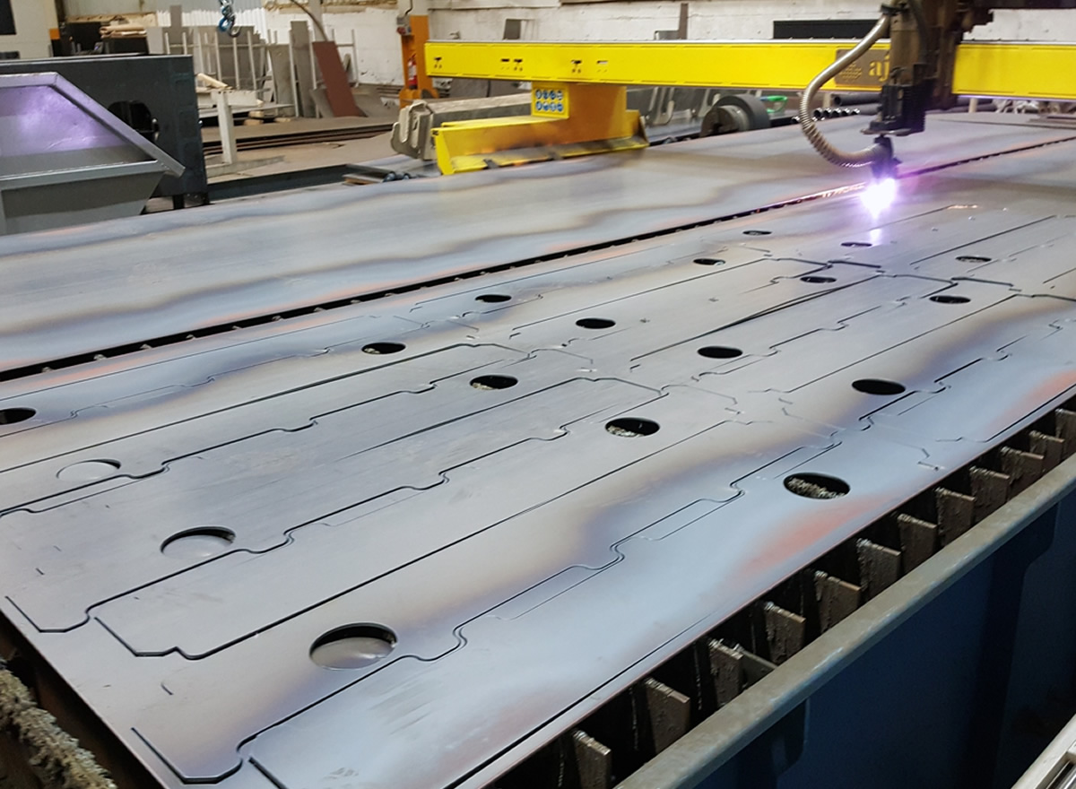
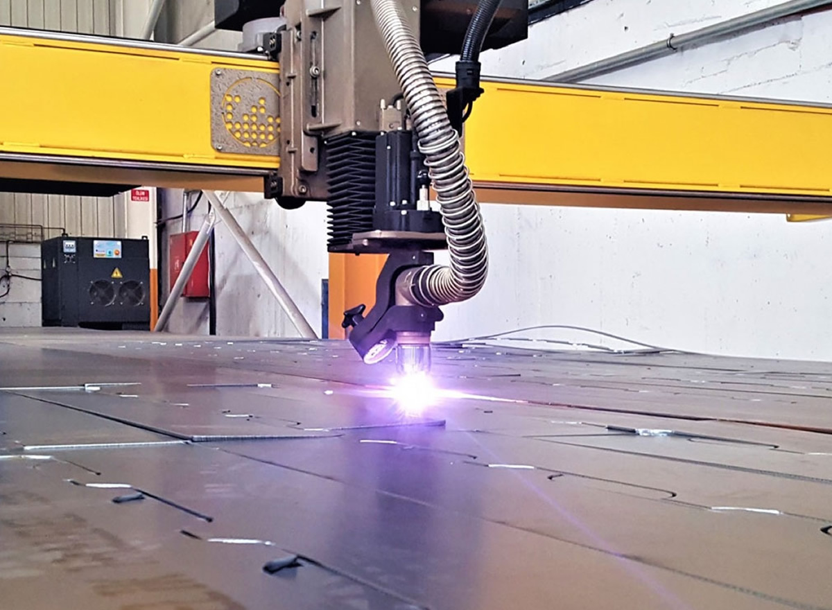
We do this plasma cutting with the help of a thermal saw. Plasma-oxygen cutting is simply ionizing the gas flowing in the torch partially by energizing it, in other words transforming it into plasma, the resulting high-temperature plasma shifting from the nozzle mouth to the positive pole material with the effect of the gas flow, melting the material, namely the metal, and removing the melting material by jet effect. performed with. Most commonly, metal sheets with a thickness of 1-80 mm (optimum 1-32mm) are cut in the plasma sheet cutting process in the industry. The industrial parts that benefit most from plasma cutting are railways, wagon industry, shipbuilding industry, (shipyards), mechanics, pressure vessel manufacturers (degasser, water tanks, hot water boilers impregnation, heating boilers).
Plasma Sheet Cutting System
In general, a plasma sheet cutting system for automation should have the following elements
Non-Carrying Arc Method
Another plasma cutting method is the non - carried arc method.Torch technology is different in this technology.The plasma arc starts between the nozzle and the electrode before it is transferred to the material, that is, the metal to be cut or drilled, and the plasma comes out in the form of a flame at the torch tip without losing its continuity with the effect of flowing gas.Generally, this method is used for non - metal materials.It is suitable to be used in surface coating process.Materials we can cut in plasma cutting process: Alloy steel, stainless steel, carbon steel, aluminum alloys, titanium and copper and alloys are cut.Metal sheets and pipes with Nickel Titanium and its alloys may only be suitable for cutting and preparing the material before machining.In plasma cutting of these metal materials, roughness and color change is observed on the cutting edge and surface.During plasma cutting of metals, combinations of plasma gases, flow rates of gases and thickness of metal material affect the cutting quality.Various gases and mixtures are used as carrier and shielding gas to achieve a good cut quality in CNC plasma cutting systems.The ionization energies between the plasma cutting gases to be used depend on the thermal conductivity and reactivity properties.
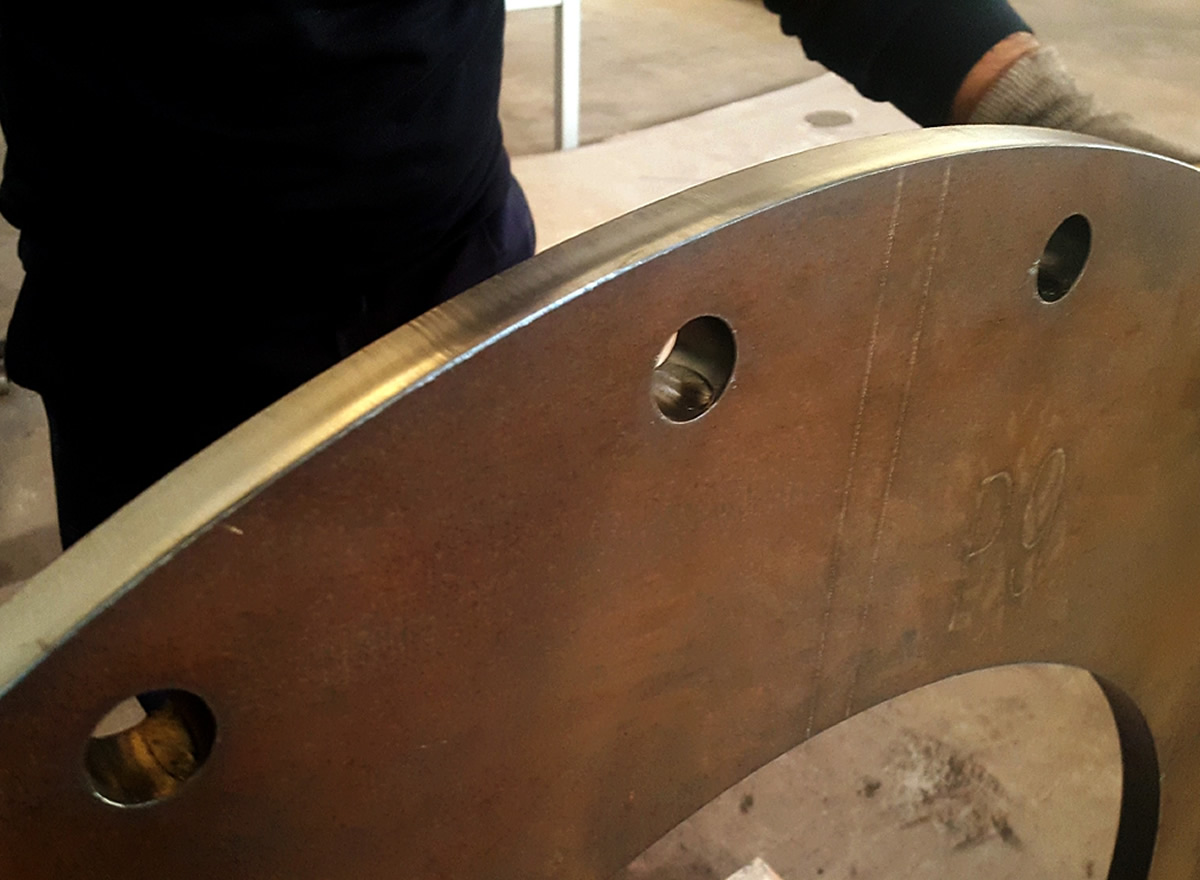
Nitrogen, oxygen, and argon-hydrogen gases are the most used gases. The standards that determine the quality in CNN plasma cutting are thermal cutting standards such as ISO9013, DIN 2310. Cutting surface angle (steepness) and smoothness, as well as cutting edge roundness, beard formation, upper fallout and slit spacing are the most important criteria that determine the quality in CNN plasma cutting. In CNC plasma cutting, the cutting surface angle is the amount of curvature that occurs on the cutting surface. It is generally determined by the steepness value. To give practical values, the slope in CNC plasma cutting varies between 1-3 degrees on the material side and 3-8 degrees on the inert material side. In straight flow torches, a cutting angle of 4-8 degrees is considered normal.